


Core Value
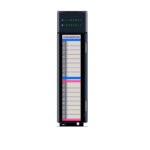
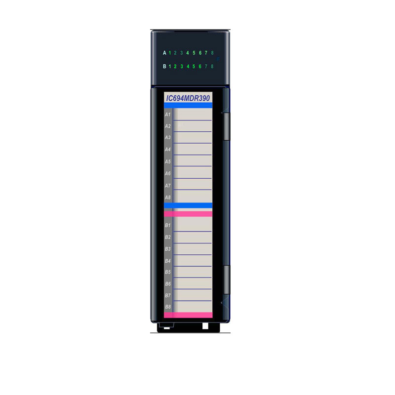
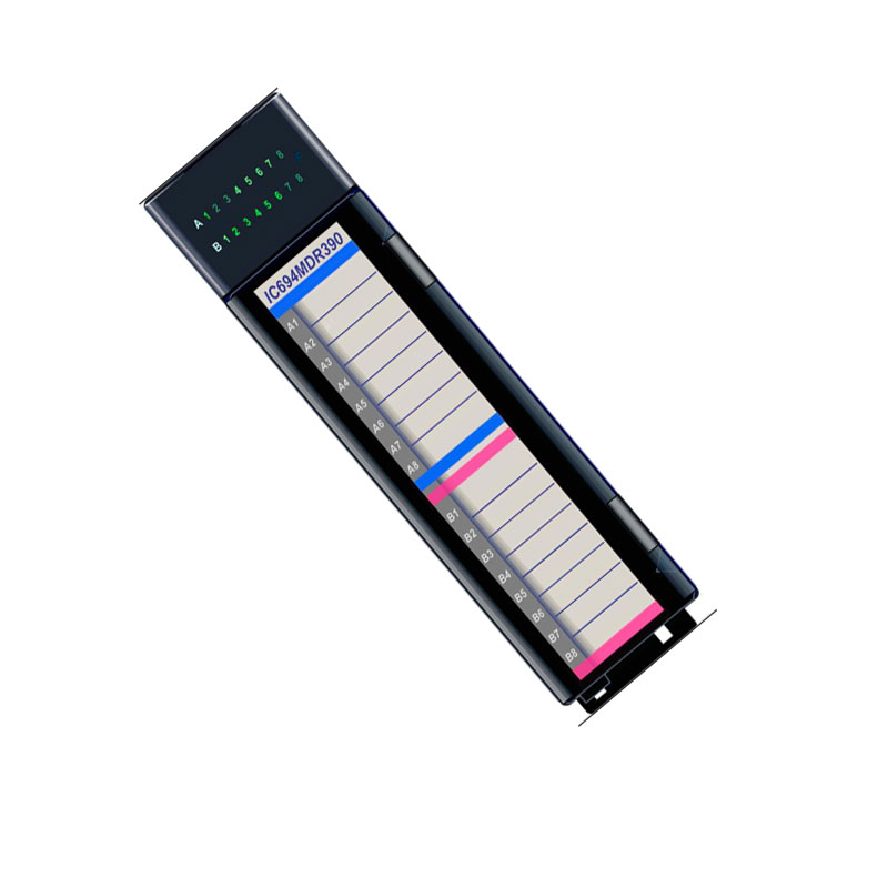
The IC694MDR390 GE solves a critical engineering challenge in heavy industries like oil and gas, chemical processing, and manufacturing. This mixed I/O module combines eight isolated inputs and eight isolated relay outputs in one compact slot. Consequently, it reduces wiring complexity and panel space while maintaining high noise immunity. Engineers rely on its 500 VAC isolation to protect field devices from ground loops and transient surges. Therefore, the module ensures stable operation in harsh environments where signal integrity is paramount.
Technical Insights
Three key parameters directly impact production efficiency and equipment lifespan. First, the response time of 15 milliseconds allows the module to switch loads quickly without bouncing contacts, which extends relay life in high‑cycle applications. Second, the inrush rating of 5.0 Amps handles capacitor charging or motor start‑up currents, preventing false trips and nuisance downtime. Third, the operating voltage range from 5 to 30 VDC or 5 to 250 VAC offers flexibility for both DC sensors and AC actuators, reducing the need for extra signal converters. Furthermore, the 16 individual LED indicators simplify troubleshooting by showing real‑time status of each input and output point. Specifically, this visibility lets operators identify faults within seconds, minimizing machine idle time. In contrast, modules without per‑point LEDs require manual voltage checks, which take longer and increase risk.
Installation and Maintenance Guide
Based on field experience, follow these three practical recommendations for reliable long‑term performance. First, always mount the IC694MDR390 GE in an RX3i I/O backplane slot that provides adequate airflow; avoid placing it near high‑heat power supplies. Secondly, use twisted‑pair cables for input wiring to reduce electromagnetic interference, especially when running long distances near motors or VFDs. Thirdly, periodically clean the module’s front panel with a dry cloth to remove dust that can obstruct LED visibility or cause heat buildup. Additionally, apply the external 24 VDC supply to the output group terminals before testing relay loads; this step prevents false activation due to residual charge. If an output fails, check the common fuse or verify that the load current stays below the 2.0 Amp limit. These practices help maintain the module’s isolation integrity and extend its operational life beyond five years.
B2B Buyers FAQ
Question: What external power supply does the IC694MDR390 GE require for its output side?
Answer: The module needs a user‑supplied DC or AC source ranging from 5 to 30 VDC or 5 to 250 VAC. This external supply powers the relay coils independently from the backplane draw.
Question: Can the IC694MDR390 GE be hot‑swapped in a running system?
Answer: No, this module does not support hot insertion or hot removal. Always power down the rack before installing or removing the IC694MDR390 GE to avoid damage.
Question: How does the module handle high inrush currents from inductive loads?
Answer: Each relay output can withstand up to 5.0 Amps of inrush for 15 milliseconds. This design accommodates the starting surge of small motors or solenoids without welding the contacts.
Question: What is the minimum load current required for reliable relay operation?
Answer: The output circuits need a minimum load of 10.0 milliamps. Below this threshold, the relay contacts may not wear cleanly, leading to early failure in low‑current applications.
Question: Where can I find the wiring diagram and LED status meanings for this module?
Answer: The OEM instruction manual is available upon request from us. It details terminal assignments, LED blink patterns, and typical connection examples for the IC694MDR390 GE.
This procurement guide provides engineering‑grade insights for the IC694MDR390 GE. Contact our team for current lead times and volume discounts. We ship from Shenzhen via FedEx, UPS, or DHL within 24 hours of confirmation.


Leave a Reply