
Product Overview
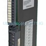
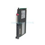
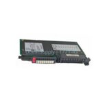
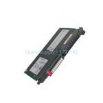
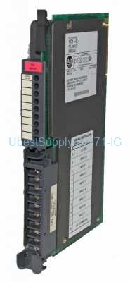
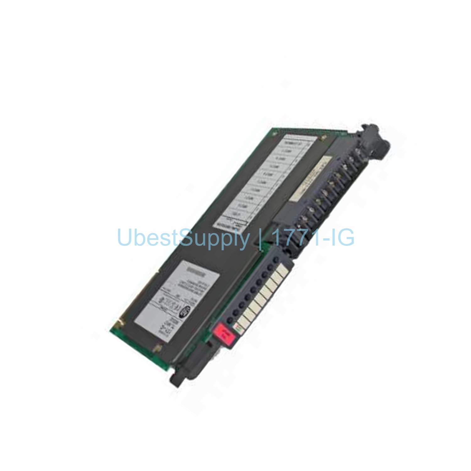
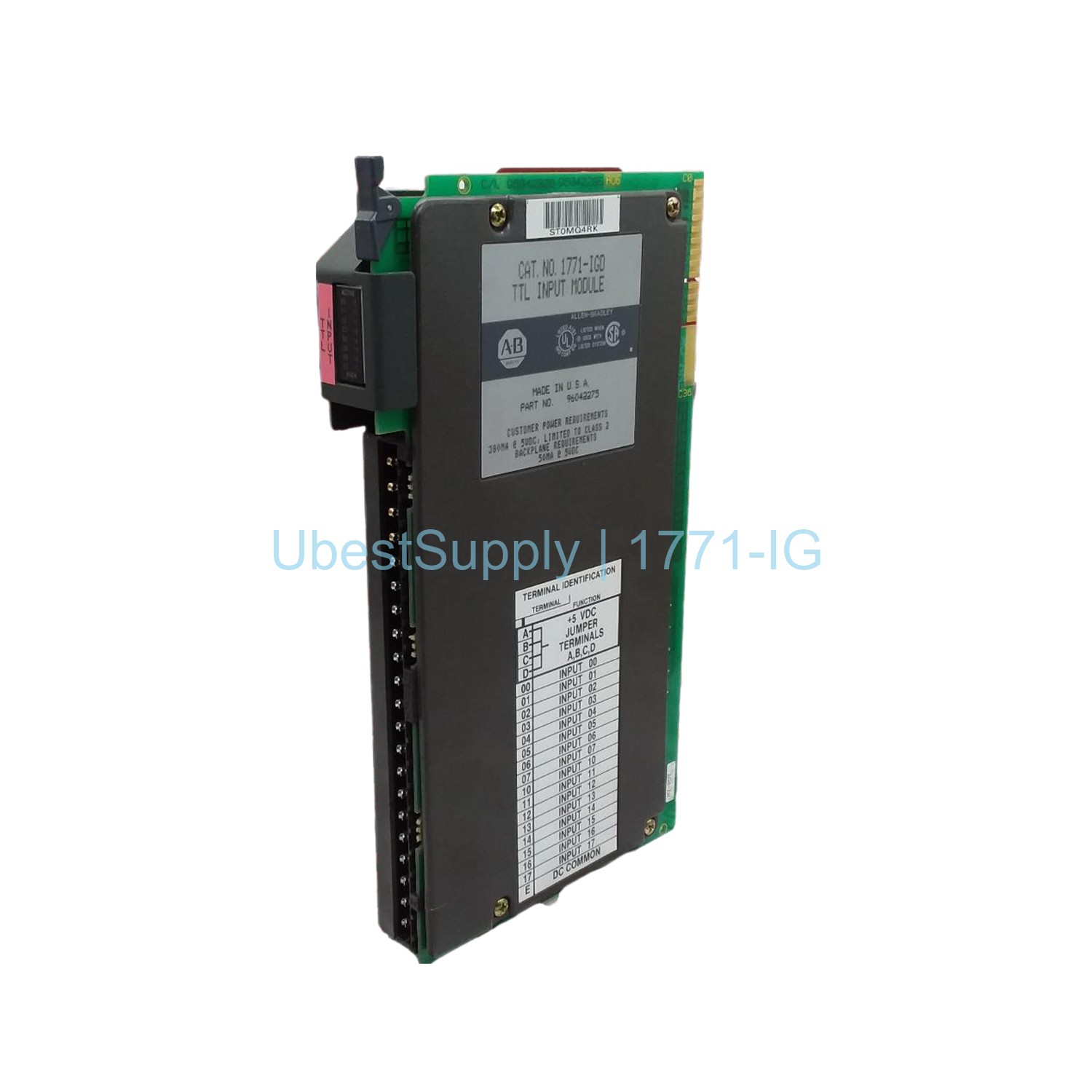
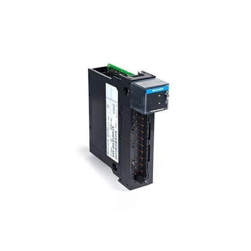
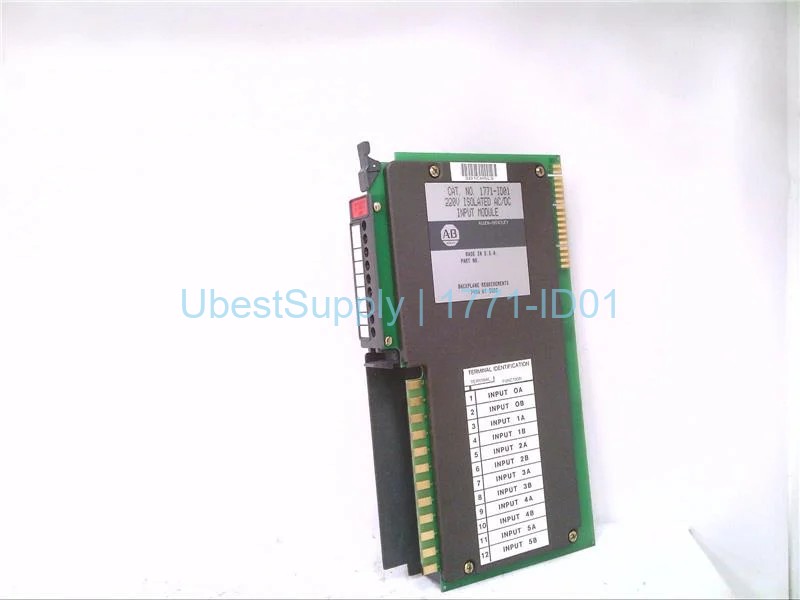
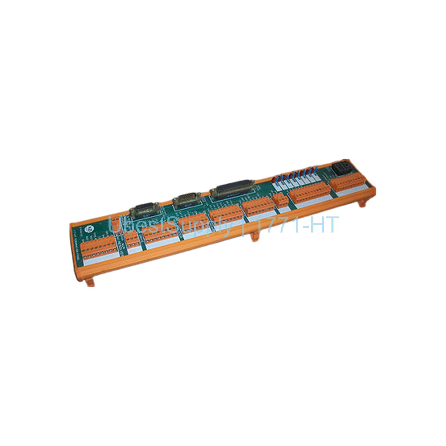
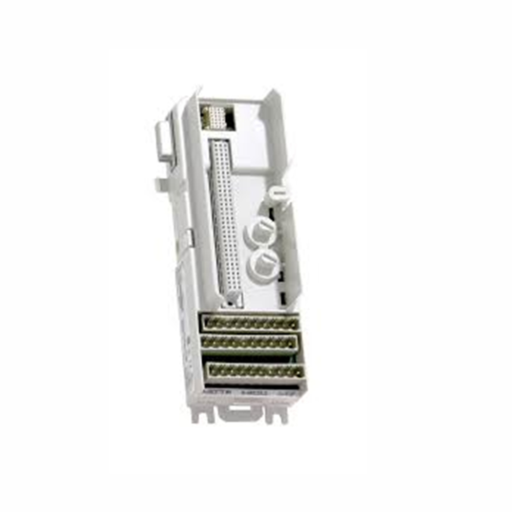
The Allen-Bradley 1771-IG is a digital DC input module. It belongs to the PLC 5 series from Rockwell Automation. This module converts DC signals from user devices. It changes them to the logic level the processor needs. It controls bit states in the PLC data table. The 1771-IG offers a modular design. It saves space and is cost-effective. You can add inputs to a control system easily. It includes a 1771-WC wiring arm. This arm allows module replacement without disconnecting wires. The module is Series A. It supports 1/2, 1, and 2-slot I/O addressing. It works with TTL interfaces and BCD encoders.

Application Scenarios
You can use the 1771-IG in many industrial automation tasks. It works well with TTL-level digital signals. Common applications include connecting encoders and sensors. It also works with push buttons and selector switches. The module fits in a 1771 I/O chassis. It works with any PLC processor. Use it in machine control, packaging lines, and material handling. Its fast response time suits high-speed counting applications. The conformal coating protects against harsh environments.
Technical Specifications
Manufacturer: Rockwell Automation. Brand: Allen-Bradley. Part Number: 1771-IG. Module Type: Digital DC Input Module. Number of Inputs: 8. Voltage Category: 5 V DC, TTL. DC Operating Voltage: 5.0 – 5.3 V. Backplane Current: 122 mA. Maximum Customer Supply Current: 500 mA. Typical DC Signal Delay (On): less than 1 ms. Typical DC Signal Delay (Off): 20 ms (+/- 9 ms). Typical AC Signal Delay (Off): 24 ms (+/- 10 ms). Wiring Arm: 1771-WC. Coating: Conformal Coat. Power Dissipation: 3.3 W. Thermal Dissipation: 11.3 BTU/hr. It requires two power sources: the I/O chassis backplane and a 5 V DC supply for TTL signals. It has optoelectrical isolation. Input filtering reduces electrical noise. Eight status indicators show TTL voltage on the front panel.

Installation & Maintenance Guide
Follow these steps to install the 1771-IG module. First, ensure the power is off. Insert keying bands between pins 34 and 36 on the upper connector. Insert bands between pins 4 and 6 on the lower connector. Place the module into an empty slot in the 1771 I/O chassis. Secure it with the locking tabs. Connect the 1771-WC wiring arm. Wire the user devices to the terminal block. Provide a 5 V DC power supply for the TTL signals. Verify the backplane power is on. Check the status indicators for correct operation. To remove the module, disconnect the power. Release the wiring arm and slide the module out. No need to disconnect field wiring.
Packing List
Each package includes: One Allen-Bradley 1771-IG module. One 1771-WC wiring arm. One installation instruction sheet. Keying bands are included. The module is shipped in an anti-static bag. Shipping is via Fedex, UPS, or DHL. Please order spare keying bands separately if needed.

.jpg)


Leave a Reply