
Product Summary
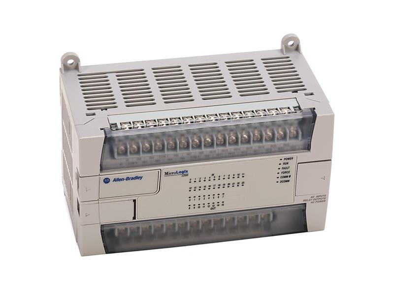
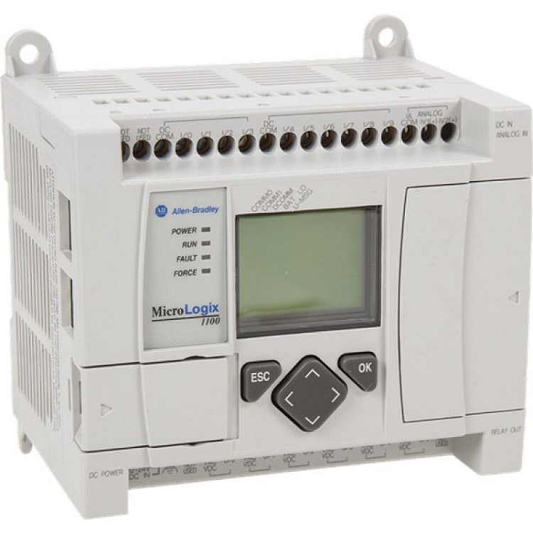
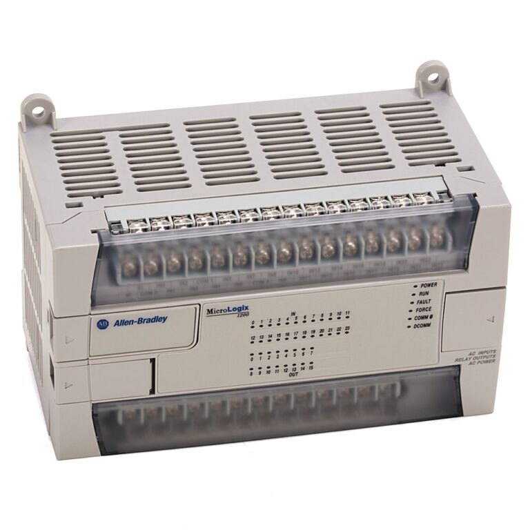
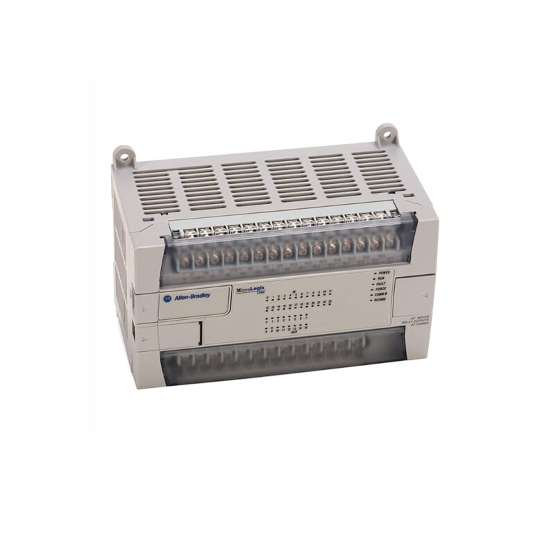
The 1762-L24BXBR MicroLogix 1200 controller delivers a compact, powerful solution for mid-range automation tasks. It integrates ten standard and four fast inputs. This unit supports five relay and four FET outputs for versatile machine control. Engineers gain high-speed counting and precise actuator management.
Buyer Guide for the Allen-Bradley 1762-L24BXBR
This controller solves critical panel space constraints with its small footprint. Its dimensions of 90 mm by 160 mm save valuable enclosure room. Procurement managers must verify the 24VDC power supply requirement for their system. This model directly replaces older 24-point racks with a unified design.
The input circuit types accept sink or source 24VDC signals. This flexibility simplifies wiring to various sensors and switches. The 1762-L24BXBR features four fast inputs accepting signals up to 20 kHz. This capability makes it ideal for high-speed counting applications.
Outputs include five relay contacts rated for 10 Amps. These handle high inrush loads like contactors and solenoids reliably. Four FET outputs provide solid-state switching for DC loads. A dedicated high-speed FET output manages pulse trains or precise positioning.
The primary communication port supports DH-485 and Modbus protocols. This enables seamless integration with existing SCADA or HMI networks. A secondary programming port allows quick online edits without disrupting the main bus. The built-in real-time clock schedules time-based control events effectively.
Installation requires only a 2-inch clearance on all sides for cooling. This compact assembly prevents heat buildup in dense cabinets. The unit supports up to six expansion modules for future I/O growth. You can add up to 96 additional I/O points as needed.
Step-by-Step Installation Guide
Begin by mounting the controller on a 35 mm DIN rail. The latching mechanism secures the unit firmly in place. Alternatively, you may use panel mounting with screws through the tabs. Panel mounting offers less vibration resistance than the DIN rail method.
Apply 24VDC power to the dedicated supply terminals. The power supply usage is 82 VA with a specified inrush current. Use properly sized circuit protection to avoid nuisance trips. Connect your field devices to the removable terminal blocks.
Wire the ten standard inputs to your pushbuttons and sensors. The four fast inputs should connect to your encoder or proximity switch. Use shielded cable for high-speed signals to maintain signal integrity. Wire the relay outputs for your AC or DC loads up to 10 Amps.
For FET outputs, ensure the load is within the 24VDC rating. Connect the high-speed FET output to a stepper drive or servo controller. Commission the device using the RSLogix 500 programming software. Download the configuration via the front-panel programming port.
Logistics & Standard Packaging Details
- One (1) Allen-Bradley 1762-L24BXBR MicroLogix 1200 Controller
- One (1) Removable Terminal Block set for I/O wiring
- One (1) Product Documentation and Safety Sheet
- Express delivery is available via FedEx, UPS, and DHL.